English
 中文简体
中文简体

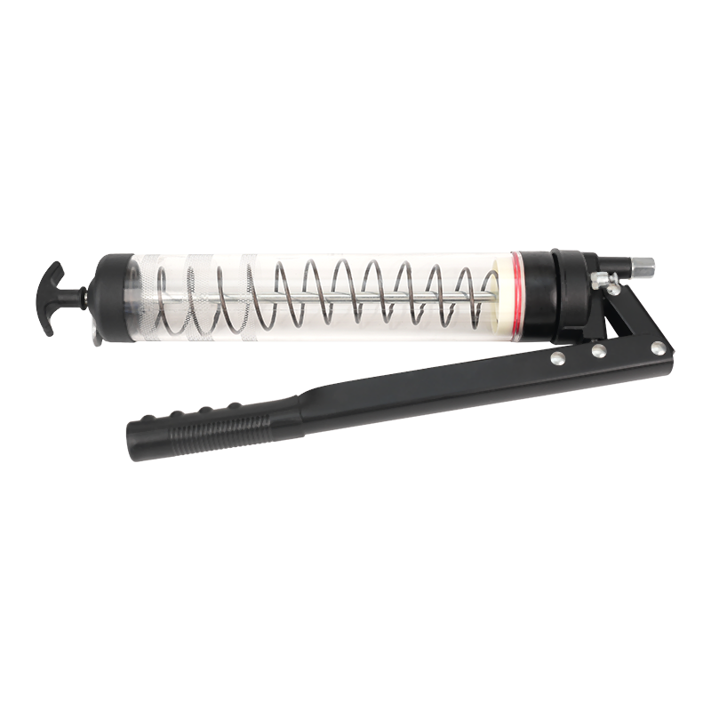
Selecting the proper fluid transfer equipment is essential for maintaining mechanical power transmission systems, automotive drivelines, and industrial machinery. Among the various manual fluid handling instruments available to technicians and mechanics, the oil suction gun serves as a primary tool for extracting and injecting heavy lubricants. This manual fluid transfer tool operates on basic mechanical vacuum principles, allowing operators to draw fluid out of tight sumps or inject high viscosity gear lube into restricted fill ports where gravity pouring is physically impossible. Understanding the mechanical operation, fluid dynamics, correct handling techniques, and thorough maintenance procedures associated with an oil suction gun ensures efficient fluid service while protecting internal machinery components from contamination.
Fundamental Mechanics and Operating Principles of the Oil Suction Gun
The functional design of an oil suction gun centers on positive displacement atmospheric pressure differentials created inside a closed cylindrical barrel. While visually resembling a standard grease gun, the internal architecture of an oil suction tool differs significantly to accommodate low to high viscosity liquid lubricants rather than semi-solid grease.
Hydraulic Suction Dynamics in Fluid Extraction
The extraction process executed by an oil suction gun relies on manual atmospheric displacement. When the operator pulls the T-bar handle backward, the internal piston moves away from the discharge orifice toward the rear end cap. This movement expands the internal volumetric capacity of the sealed barrel, creating a low pressure vacuum zone in front of the piston head.
External atmospheric pressure acting upon the surface of the fluid inside the target reservoir forces the liquid up through the attached flexible hose or rigid metal nozzle and into the expanding barrel chamber. The speed and efficiency of this draw stroke depend directly on the fluid viscosity, the ambient temperature, the internal diameter of the suction tube, and the structural integrity of the piston seals. When handling thick fluids like SAE 90 or SAE 140 gear lubricants, the mechanical resistance during the draw stroke increases, requiring steady physical effort to maintain fluid momentum without pulling air past the piston lips.
Internal Construction and Sealing Assembly
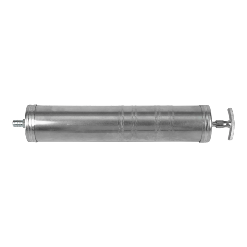
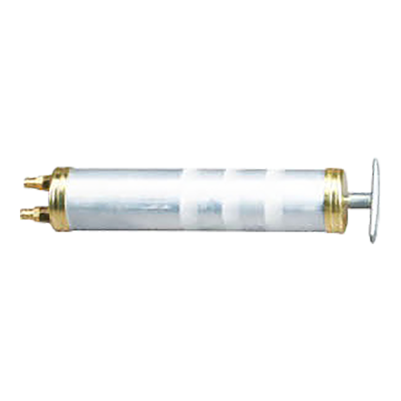
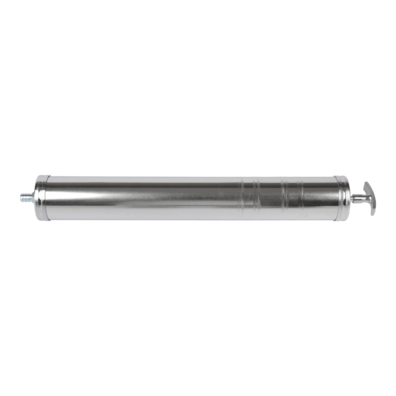
An oil suction gun consists of a heavy duty steel or aluminum cylindrical barrel, a threaded front end cap, a flexible transparent tube or rigid discharge pipe, and an internal plunger shaft connected to a rear T-handle. The primary internal component responsible for vacuum creation is the piston head, which typically features dual cup seals or specialized synthetic elastomer rings made from Nitrile Butadiene Rubber or Neoprene.
Unlike a standard grease gun, an oil suction tool features no internal follower spring or ratcheting pressure mechanism. The piston assembly moves freely along the smooth inner walls of the polished cylinder, driven entirely by manual push and pull forces exerted by the operator. The front end cap contains a threaded port that receives the flexible delivery hose, forming an airtight seal to prevent atmospheric air leakage into the vacuum chamber during the suction stroke.
Fluid Compatibility Profiles for Mechanical Extraction
The operational versatility of an oil suction tool extends across a wide spectrum of petroleum based and synthetic fluids. The tool excels at handling heavy differential oils, manual transmission fluids, transfer case lubricants, industrial gear oils, hydraulic oils, and engine crankcase oils.
However, fluid compatibility is governed by the chemical resistance of the internal elastomer piston seals and flexible vinyl tubing. Standard nitrile or neoprene seals tolerate mineral oils, synthetic gear lubes, and petroleum distillates exceptionally well. Conversely, aggressive chemicals such as glycol based brake fluids, harsh bio-based solvents, or strong esters can cause standard rubber seals to swell, soften, or degrade prematurely. Operators must verify that the internal seal composition of the fluid suction tool aligns with the specific chemical characteristics of the liquid being transferred.
Essential Preparation and Workplace Safety Protocols
Proper setup and safety preparation prevent accidental chemical exposure, equipment damage, and workplace contamination during fluid transfer procedures. Working with petroleum lubricants demands adherence to personal protection standards and clean work practices.
Personal Protective Equipment and Environmental Safeguards
Prior to initiating any fluid service using an oil suction gun, operators must equip appropriate personal protection gear. Safety glasses with side shields protect eyes from high pressure fluid splatters that can occur if a hose dislodges under pressure. Heavy duty nitrile or neoprene gloves prevent prolonged skin contact with warm or contaminated lubricants, which often contain metallic wear particles, combustion byproducts, and chemical additives.
Environmental preparation involves safeguarding the immediate work floor from accidental fluid drips or spills. Placing an oil resistant drain pan directly beneath the fluid transfer site catches residual drops when moving the suction nozzle between the reservoir and the waste container. Covering surrounding floor surfaces with absorbent spill mats prevents slip hazards and contains unexpected leaks during high volume fluid extraction cycles.
Tool Inspection and Pre Operational Check
Before inserting an oil suction tool into clean lubricant or dirty sumps, a comprehensive tool inspection must be performed. The operator should inspect the outer barrel for dents or deep scratches that could distort the inner cylinder surface and prevent the piston from creating a continuous vacuum seal.
The flexible delivery hose must be checked for cracks, hardening, or internal blockages. Ensure the hose fits tightly over the barbed fitting or threaded front end cap adapter. A loose hose connection allows air to enter the chamber during extraction, causing cavitation and reducing total suction volume. Furthermore, the operator should pull and push the T-handle manually while feeling for smooth, uninterrupted motion. Excessive binding suggests internal debris or dried lubricant residue that requires thorough cleaning prior to use.
Preparing the Vehicle or Machinery Fluid Reservoir
Accessing differential housings, transfer cases, manual gearboxes, or industrial gear reducers requires preparing the fill and drain ports correctly. Surrounding dirt, road grime, grit, and loose debris must be thoroughly cleaned from the fill plug area using a stiff wire brush and aerosol brake cleaner prior to loosening the plug.
Failure to clean the surrounding surface risks knocking abrasive dirt particles directly into the fluid cavity when the plug is removed. Once the area is clean, the operator should always loosen and remove the upper fill plug prior to removing the bottom drain plug or inserting the suction hose. Verifying that the fill plug can be safely removed ensures that the machinery will not be drained of oil without a verified path for refilling fresh lubricant.
Step by Step Operation for Fluid Extraction
Extracting fluid from an enclosed housing or sump requires precise execution to maximize the fluid volume pulled during each stroke while minimizing air entrainment and accidental spills.
Accessing the Reservoir and Position Setup
Begin by inserting the flexible hose of the oil suction gun directly through the open fill or inspection port of the fluid housing. Snake the hose downward toward the lowest point of the sump cavity where settled fluid and particulate matter reside.
Position the metal barrel of the oil suction tool as close to the entry port as practical while maintaining a stable grip. Holding the barrel in a slightly downward inclined angle allows fluid to collect naturally near the inlet cap, helping to keep the flexible hose completely submerged below the fluid surface throughout the extraction stroke.
Executing the Vacuum Draw Stroke
Grasp the barrel body firmly with one hand while using your dominant hand to grip the T-handle. Pull the handle backward in a smooth, steady, and continuous motion. Avoid quick jerking movements, as rapid plunger movement in high viscosity oil creates a severe pressure drop that can cause air to bypass the piston seals or submerge hose turbulence that pulls air pockets into the stream.
As the handle approaches full extension, hold the position for three to five seconds. High viscosity fluids move slowly through narrow suction tubes, and allowing this brief pause gives the low pressure vacuum inside the barrel time to pull the remaining fluid through the hose until internal pressure equalizes with the atmosphere.
Managing Capacity and Fluid Level Verification
A standard oil suction gun holds approximately five hundred milliliters or sixteen fluid ounces of liquid per full stroke. When servicing larger gearboxes or differential housings that hold multiple liters, extraction must be completed in successive steps.
Once the barrel reaches full capacity, carefully withdraw the flexible hose from the fluid port, tilting the hose tip upward immediately to prevent residual oil from dripping onto external surfaces. Insert the hose tip deep into an approved waste oil container or temporary collection jug. Depress the T-handle steadily to discharge the extracted fluid from the barrel. Repeat this extraction cycle until the sump is empty or the desired fluid extraction level is reached.
Step by Step Operation for Fluid Injection and Transfer
Filling tight fluid housings on automotive undercarriages or industrial machinery presents significant physical access challenges. The oil suction tool serves as an effective hand pump for transferring fresh lubricant from open supply containers into elevated or horizontal fill ports.
Priming and Air Bleeding Techniques
To prepare the tool for fluid injection, submerge the clean flexible hose into a container of fresh lubricant. Pull the T-bar handle backward slowly to fill the barrel completely with clean oil.
Once the barrel is filled, point the front hose fitting upward vertically and push the handle forward slightly until a solid stream of fluid appears at the hose tip. This simple purging step forces trapped air pockets out of the upper cylinder and flexible tubing, ensuring accurate volumetric fluid delivery and eliminating messy air spattering when filling restricted gear cases.
Position Setting for Overhead or Restricted Fill Ports
Guide the flexible delivery tube into the designated fill port of the differential, transmission, or gearbox. Ensure the tube extends far enough into the housing so that it remains securely positioned inside the cavity without slipping out during the injection stroke.
When working in tight undercarriage spaces, maneuver the flexible hose around obstacle components such as exhaust pipes, sway bars, and frame crossmembers. The flexible nature of the vinyl tubing allows the operator to reach fill plugs that cannot be accessed using rigid funnel spouts or standard lubricant squeeze bottles.
Executing the Controlled Discharge Stroke
Hold the main barrel securely against a stable frame member or hold it firmly with both hands. Depress the T-handle smoothly and evenly, pushing the piston forward to discharge the fluid into the reservoir.
Monitor the force required to depress the handle. If resistance rises suddenly, check the hose tip to ensure it has not pressed flat against an internal gear or housing wall, which can block the fluid outlet. Continue transferring fresh oil in full barrel increments until lubricant begins to trickle slowly back out of the bottom edge of the fill port, signaling that the fluid level has reached the correct manufacturer specification.
Tactical Applications in Automotive and Industrial Maintenance
The unique design of a manual fluid suction tool makes it indispensable across diverse mechanical maintenance scenarios where conventional fluid pumps or gravity feeding methods are ineffective.
Servicing Automotive Differentials and Transfer Cases
Rear differential housings on modern trucks, passenger cars, and sports utility vehicles frequently feature removable fill plugs but lack bottom drain plugs. Servicing these components requires pulling old, heat stressed gear oil out through the fill hole before fresh lubricant can be added.
An oil suction gun allows technicians to reach down into the lowest contours of the differential housing, extracting contaminated oil along with suspended metallic wear particles. Furthermore, four wheel drive transfer cases are often situated directly above crossmembers where overhead space is severely limited. The flexible hose of an oil suction tool navigates these cramped clearances easily, delivering fresh synthetic gear lube without requiring the removal of major driveline components.
Industrial Gearbox and Hydraulic Sump Maintenance
Industrial manufacturing environments feature stationary machinery such as milling machines, lathes, mechanical presses, and right angle gear reducers that require periodic oil changes. Many small to medium industrial gearboxes lack dedicated internal pumps and utilize small sight glasses to monitor fluid levels.
The oil suction tool acts as a portable maintenance device for plant technicians, enabling rapid fluid sampling, precise topping off of low gearboxes, and complete extraction of degraded fluid from tight machine sumps during scheduled preventative maintenance turnarounds.
Small Engine and Marine Powerplant Fluid Extraction
Small four stroke engine equipment such as lawn tractors, pressure washers, and commercial generators often feature oil drain ports that drop oil directly onto frame rails, creating substantial cleanup challenges. Marine inboard and outboard engines present an even greater challenge, as the engine block sits low in the vessel hull, rendering bottom drain plugs completely inaccessible.
Utilizing a fluid suction tool allows maintenance personnel to extract warm engine oil directly through the dipstick tube or fill cap. This top down extraction method completely avoids messy under engine spills, keeping engine compartments and boat bilges completely clean.
Comparative Analysis of Manual Fluid Handling Devices
Choosing the correct manual fluid handling tool requires evaluating operational characteristics, flow capacities, physical limitations, and maintenance complexity across different device types.
|
Fluid Transfer Device |
Ideal Viscosity Range |
Primary Use Case |
Flow Rate Capability |
Maintenance Complexity |
|---|---|---|---|---|
|
Manual Oil Suction Gun |
Medium to High Viscosity |
Spot Extraction and Tight Port Injection |
Low Volumetric Flow |
Low Maintenance Requirements |
|
Hand Lever Transfer Pump |
Low to Medium Viscosity |
High Volume Drum and Bucket Transfer |
High Volumetric Flow |
Moderate Maintenance Needs |
|
Siphon Hose Tube |
Very Low Viscosity |
Gravity Dependent Downward Transfer |
Variable Flow Rate |
Minimal Maintenance Needs |
|
Vacuum Fluid Extractor |
Low to Medium Viscosity |
Large Sump Extraction via Continuous Vacuum |
Continuous Medium Flow |
Moderate to High Maintenance |
Maintenance, Cleaning, and Storage Guidelines
To ensure consistent vacuum performance, prevent premature piston seal failure, and avoid cross contaminating sensitive fluid systems, an oil suction gun must be cleaned, inspected, and stored properly after every maintenance procedure.
Post Operation Flushing and Degreasing Procedures
Once fluid transfer tasks are complete, the internal cylinder and hose must be thoroughly cleared of lingering fluid residue. Wipe the exterior metal surfaces clean with a shop towel to remove oily film and grime.
To flush the internal chamber, submerge the flexible hose into a container of clean, mild solvent or warm water mixed with an oil cutting degreaser. Pull and push the T-handle several times to cycle the solvent through the barrel, dissolving heavy fluid films attached to the inner cylinder walls. Discharge the spent cleaning solution into an appropriate waste container. Finish by pumping air through the dry tool several times to clear remaining cleaning liquid from the hose and barrel.
Plunger Seal Lubrication and Storage Preparation
Rubber piston seals require proper lubrication to maintain their flexibility and structural shape over time. Storing an oil suction tool completely dry can cause synthetic rubber seals to harden, shrink, or adhere to the inner metal cylinder walls, resulting in seal damage during subsequent use.
Before storing the tool, apply a few drops of clean mineral oil or light machine oil directly onto the piston head inside the barrel. Cycle the handle back and forth several times to distribute a light protective film across the entire internal cylinder surface. This simple step preserves the elasticity of the elastomer lip seals, preventing vacuum loss during future applications.
Component Inspection and Seal Replacement Procedures
Over extended periods of use, internal rubber seals wear down from friction against the cylinder walls, leading to diminished suction performance or internal bypass leakage. If the tool fails to draw fluid despite a fully submerged hose, the piston seal assembly must be inspected.
Unscrew the front and rear end caps to remove the internal plunger rod and piston assembly. Examine the rubber cup seals for fine cuts, ragged edges, or material erosion caused by metal particulate abrasion. Damaged seals should be replaced with compatible replacement seal kits. When reassembling the tool, inspect the threaded end cap connections, ensuring that front cap O-rings are intact and securely seated to prevent atmospheric air leakage into the main suction body.
Proper Storage Orientation and Environmental Protection
Store the oil suction gun in a clean, dry, and dust free storage cabinet. The tool should ideally be stored hanging in a vertical position with the hose end pointing downward, or laid flat inside a dedicated tool tray lined with oil absorbent padding.
Hanging the tool vertically allows any residual oil droplets to drain naturally toward the discharge port rather than collecting around the rear shaft seal. Avoid leaving the suction tool in direct sunlight or near high temperature heat sources such as shop heaters, as excessive thermal exposure accelerates rubber seal oxidation and warps flexible vinyl tubing.
Troubleshooting Common Operational Issues
Even well maintained fluid suction tools can occasionally experience operational difficulties during fluid extraction or injection procedures. Identifying mechanical symptoms quickly allows operators to rectify issues without interrupting maintenance workflows.
Loss of Suction Vacuum During Extraction
If the T-handle is pulled backward but no fluid enters the flexible hose, the tool has lost internal vacuum seal integrity. The most common cause is a loose front cap fitting or a damaged flexible hose connection that permits air to enter the chamber far easier than heavy fluid can be drawn up the tube.
To resolve this issue, check that the front end cap is securely threaded onto the barrel and ensure the flexible hose is pushed tightly over the barbed fitting. If the connection is secure but vacuum remains poor, verify that the hose tip remains fully submerged beneath the fluid surface throughout the draw stroke. If air bubbles continue to enter the barrel, inspect the internal piston cup seals for physical wear or seal inversion.
Excessive Resistance During Handle Movement
When working with cold, high viscosity gear lubricants, the physical force required to pull or push the T-handle increases significantly. However, if the handle becomes nearly impossible to move, a mechanical restriction is likely present within the fluid path.
Inspect the flexible hose for kinks, sharp bends, or internal clogs caused by debris pulled from the bottom of the gear housing. Straighten the hose path and verify that the hose inlet tip is not jammed flat against an internal wall or gear face inside the machine cavity. If the hose is completely unobstructed, slightly warming the supply fluid container in a controlled, warm environment will reduce fluid viscosity and restore normal pumping operation.
Fluid Bypass Behind the Piston Shaft
If fluid leaks out around the rear end cap or along the T-handle shaft during the discharge stroke, lubricant is bypassing the internal piston head. This condition indicates that the piston seals are either worn, misaligned, or chemically degraded by incompatible fluids.
Disassemble the barrel and clean all internal components thoroughly. Inspect the rubber cup seals for swelling, cracking, or edge deformation. Replace worn piston seals with fresh oil resistant rubber components. When servicing the piston assembly, ensure the seal lips face toward the front discharge cap to properly cup the fluid load and form a tight seal against the inner cylinder walls during forward discharge movements.