English
 中文简体
中文简体

Maintaining smooth mechanical operation across internal combustion engines, industrial machinery, and fluid transfer systems depends entirely on the continuous circulation of lubricants. The primary component responsible for driving this vital fluid flow is the Oil Pump. Without a functional displacement mechanism to move fluid under controlled force, metal components operating in high speed environments would experience rapid thermal escalation, severe surface friction, and catastrophic mechanical breakdown within moments of operation. Understanding the precise role of this mechanical component clarifies how mechanical assemblies sustain heavy operational loads, control internal operating temperatures, and preserve component integrity over years of continuous service.
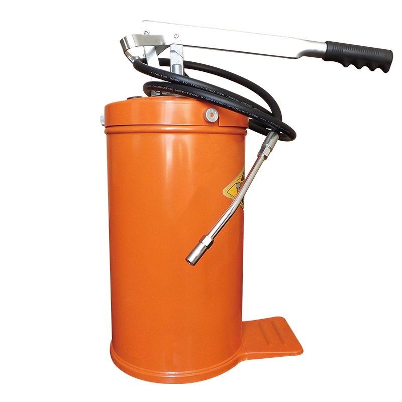
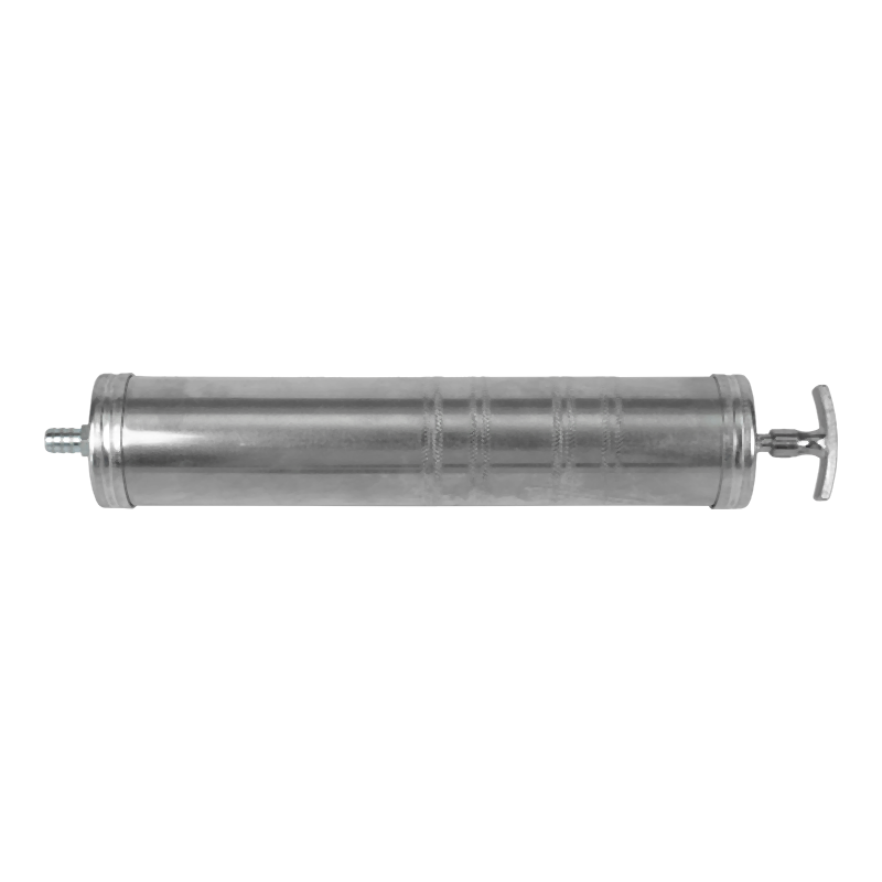
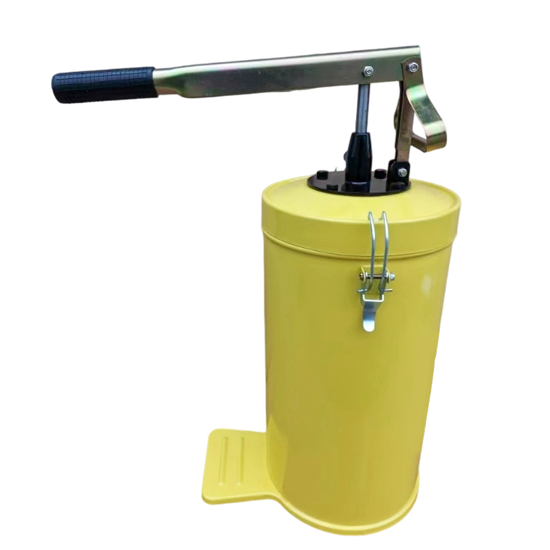
Beyond internal engine lubrication, specialized equipment known as an Oil Transfer Pump plays a major role in moving bulk fluids between storage reservoirs, processing tanks, conditioning loops, and auxiliary machinery. Both types of pumping mechanisms operate on principles of fluid displacement, yet their structural configurations, operating pressure ranges, and system roles are tailored to distinct functional objectives. Examining the mechanical principles, operational dynamics, diagnostic indicators, and maintenance requirements of these systems reveals how fluid movement preserves the working lifespan of complex mechanical infrastructure.
Primary Operational Roles of the Oil Pump in Mechanical Systems
The fundamental purpose of an Oil Pump is to transform mechanical energy from a rotating shaft into hydraulic force, continuously drawing fluid from a supply reservoir and propelling it through complex internal passageways. While many individuals view fluid circulation as a simple transport process, the actual operation involves multiple concurrent thermodynamic and physical functions that protect sensitive mechanical surfaces.
Pressurization and Fluid Displacement Principles
Fluid flow alone is insufficient to protect high speed mechanical interfaces; the fluid must arrive at friction points under active pressure. An Oil Pump operates as a positive displacement device, meaning it captures a fixed volume of fluid on its suction side and forcibly moves that fluid into a discharge zone during every rotational cycle.
As mechanical parts rotate, the internal volume of the suction chamber expands, creating a localized pressure drop relative to ambient pressure inside the fluid reservoir. Atmospheric pressure or surrounding fluid head pressure forces oil into this low pressure zone. As the internal mechanisms turn further, the physical volume contracts, pushing the captured fluid outward into distribution channels under high hydraulic pressure. This continuous displacement forces fluid through narrow oil galleries, internal filter media, and restrictive clearance spaces that would otherwise resist passive fluid entry.
Hydrodynamic Film Creation and Bearing Protection
The primary physical benefit of forced fluid distribution is the formation of a hydrodynamic wedge between moving metal surfaces. In rotating assemblies such as crankshaft main journal bearings, connecting rod journals, and camshaft bearings, metal surfaces must never physically touch during operation. Direct contact produces intense friction, rapid heat generation, and immediate material transfer that quickly destroys precision machining tolerances.
When pressurized fluid supplied by an Oil Pump enters the tiny clearance gap between a rotating journal and its stationary bearing shell, the rotational motion of the journal drags the viscous fluid into a narrowing space. This physical wedging action generates extreme localized fluid pressure within the clearance gap, literally floating the heavy steel shaft on a pressurized film of fluid only microns thick. As long as the Oil Pump maintains adequate flow and pressure, moving metal parts remain entirely separated by this liquid barrier, reducing physical surface wear to negligible levels.
Heat Absorption and Thermal Regulation
While primary cooling in internal combustion engines and large gearboxes relies on liquid coolant circuits or external air flow, the internal lubricant serves as a crucial secondary cooling medium. High speed friction, combustion chamber heat conduction, and gear mesh compression generate substantial thermal energy deep inside internal mechanical components where external cooling jackets cannot reach.
An active Oil Pump continuously sweeps cooler fluid through these thermal hot spots. As the fluid passes over heated surfaces such as piston undersides, connecting rod journals, and gear tooth contact faces, heat energy transfers into the fluid via convection. The fluid then carries this absorbed thermal energy away to an oil pan or an external fluid cooler, where heat dissipates into ambient air before the fluid returns to the suction inlet. Without this steady fluid circulation, localized thermal hotspots would quickly cause metal softening, piston seizure, and lubricant thermal breakdown.
Removal of Contaminants and Debris Transportation
Mechanical operation continuously generates microscopic wear particles, carbon soot from combustion blowby, and moisture condensate. Left unchecked inside local component clearances, these particulate contaminants act as grinding compounds, accelerating abrasive wear across precision machined surfaces.
Continuous fluid displacement driven by an Oil Pump provides an ongoing cleansing mechanism. Moving fluid washes through tight clearances, sweeping loose debris, carbon deposits, and metallic micro particles away from sensitive working areas. The fluid carries these suspended contaminants directly into a filtration unit, where porous filter media traps harmful solid matter before the fluid recirculates back into the primary gallery network.
Mechanics and Internal Architecture of the Oil Pump
Positive displacement designs dominate fluid circulation applications because they generate consistent volume flow regardless of downstream system pressure resistance. Three primary positive displacement configurations are commonly utilized inside modern machinery: external gear units, internal gerotor units, and variable displacement vane configurations.
External and Internal Gear Displacement Architectures
Gear based designs represent one of the most reliable mechanical layouts for moving viscous fluids. An external gear layout consists of two identical intermeshing gears housed within a tightly machined casing. One gear acts as the driven shaft, receiving rotational power from the crankshaft, camshaft, or an electric drive motor, while the secondary idler gear rotates in response to gear tooth engagement.
As the gear teeth unmesh on the inlet side of the pump housing, they create an expanding fluid cavity that draws fluid into the casing. Captured fluid travels around the perimeter of the housing inside the spaces between individual gear teeth and the smooth internal wall of the casing. When the rotating gear teeth mesh together again on the discharge side, the available space shrinks dramatically, forcing the fluid out through the exit port under pressure. Fluid cannot flow backward through the center because the intermeshing gear teeth form a continuous mechanical seal.
An internal gear layout utilizes an inner spur gear rotating inside a larger outer ring gear with internal teeth. A stationary crescent shaped seal divider separates the suction and discharge zones inside the pump housing. As the inner gear drives the outer gear, fluid fills the expanding spaces between the gear teeth and the crescent divider on the inlet side. The fluid is carried smoothly around both sides of the crescent divider and compressed out the discharge port as the gear teeth remesh on the opposite side.
Gerotor and Trochoidal Rotor Mechanisms
Gerotor configurations represent an advanced evolution of internal gear mechanics, widely favored in automotive engines due to their compact size, quiet operation, and smooth flow characteristics. The term gerotor derives from generated rotor, referring to the mathematically precise geometry of the internal drive components.
A gerotor assembly consists of an inner rotor with externally rounded lobes and an outer rotor with matching internal lobes. The inner rotor always features one less lobe than the outer rotor. The inner rotor is mounted on a driven shaft slightly eccentric to the center axis of the outer rotor. As the inner rotor turns, its lobes drive the outer rotor in the same direction.
Because of the offset rotational axes and differing lobe counts, the space between the inner and outer rotor lobes continuously changes volume throughout each rotation. On the inlet side, the expanding spaces between the lobes create a strong vacuum that draws fluid into the housing. On the discharge side, the contracting lobe spaces squeeze the fluid into a high pressure outlet port. The geometry ensures continuous fluid contact between the inner and outer lobes, providing internal sealing without requiring a stationary crescent divider.
Variable Displacement Vane Mechanisms
Traditional fixed displacement gear and gerotor units move a set volume of fluid per revolution, meaning fluid flow increases proportionally with engine or motor speed. At high rotational speeds, a fixed displacement unit produces far more oil volume and hydraulic pressure than the mechanical system actually requires. Excess pressure must be dumped back into the sump through a relief valve, wasting engine horsepower and creating unnecessary thermal energy inside the fluid.
Variable displacement vane mechanisms solve this energy inefficiency by actively altering pump volume based on real time system demand. A vane design features a central rotor fitted with sliding rectangular vanes that move radially inward and outward within slots. This rotor spins inside an adjustable eccentric outer ring, often called a stroke ring or slide ring.
Control hydraulics or electronic actuators shift the radial position of the stroke ring relative to the central rotor. When system pressure demands are high, the stroke ring is moved into maximum eccentricity, creating large volume chambers between the vanes that deliver maximum fluid displacement per revolution. When system demand drops or engine speed increases significantly, hydraulic pressure pushes the stroke ring toward a concentric position relative to the rotor. This action reduces the internal volume changes between sliding vanes, decreasing fluid displacement while maintaining precise system pressure control and saving substantial mechanical power.
The Distinct Role and Operation of the Oil Transfer Pump
While internal lubrication mechanisms focus on generating high internal gallery pressures within an engine or gearbox casing, an Oil Transfer Pump is designed to handle bulk fluid movement between distinct storage locations, processing vessels, or equipment reservoirs. Fluid transfer operations require specific mechanical characteristics tailored to high volume handling, suction lift capability, and adaptability across diverse fluid viscosities.
Bulk Fluid Handling Across Industrial Systems
Industrial processing facilities, fleet maintenance depots, marine vessels, and power generation plants rely heavily on specialized fluid transfer machinery. An Oil Transfer Pump moves fuel oils, heavy lubricating oils, hydraulic fluids, and waste oils across long piping distances, through vertical elevation changes, and into conditioning equipment.
These pumps handle tasks such as filling overhead day tanks from main storage bunkers, circulating oil through off line kidney loop filtration systems, draining sumps during routine maintenance overhauls, and feeding fuel directly into large industrial burners. Because transfer operations often involve moving cold, high viscosity liquids through extensive external piping networks, an Oil Transfer Pump must excel at creating strong inlet suction and managing heavy fluid friction drag without stalling its drive motor.
Managing Viscosity Variations and Suction Lift
Viscosity represents the internal friction resistance of a fluid to flow. Lubricating oils exhibit dramatic viscosity changes in response to ambient temperature fluctuations. Cold oil behaves as a thick, sluggish liquid that strongly resists movement through suction piping, whereas hot oil flows easily like light liquid.
An effective Oil Transfer Pump must maintain self priming capabilities to lift thick, cold fluids from deep underground tanks or low lying drums without losing fluid prime. Positive displacement sliding vane, flexible impeller, and progressive cavity designs excel in these applications because their internal mechanical seals generate powerful vacuum conditions inside empty suction lines. Once the pump draws liquid up into the housing, the positive displacement mechanism forces the viscous fluid through long discharge lines regardless of fluid thickness, preventing air binding and ensuring steady volumetric transfer rates.
Filtration Integration in Transfer Operations
Bulk oil stored in large tanks naturally accumulates moisture, oxidation byproducts, sediment, and fine dust over time. Transferring contaminated fluid directly into operating machinery introduces extreme risk of internal component damage. Consequently, an Oil Transfer Pump is frequently paired with high efficiency external filtration circuits, forming mobile or stationary fluid conditioning rigs.
As the Oil Transfer Pump draws fluid from a storage vessel, it pushes the liquid through multi stage particle filters, water absorbing filter elements, or centrifugal separators before the clean oil reaches the destination reservoir. Operating fluid transfer and filtration simultaneously, often referred to as kidney loop processing, ensures that replacement or auxiliary oil meets stringent cleanliness standards before entering high precision hydraulic systems or heavy machinery casings.
Comparison Between Internal Lubrication Pumps and External Transfer Pumps
The table below highlights structural, operational, and functional distinctions between internal engine pressure supply units and external fluid transfer equipment.
|
Operational Characteristic |
Internal Engine Lubrication Unit |
External Fluid Transfer Equipment |
|
Primary Objective |
Pressurize internal galleries and float bearings |
Move bulk fluid volumes between storage tanks |
|
Operational Mounting Location |
Integrated internally within engine or pump housing |
Mounted externally on baseplates or mobile carts |
|
Pressure Capabilities |
Moderate to high pressure delivery inside tight clearances |
Low to moderate pressure delivery over long pipe runs |
|
Fluid Flow Capacity |
Proportional to internal engine mechanical speeds |
Fixed or variable output based on transfer requirements |
|
Drive Mechanism Type |
Direct gear or chain drive from internal crankshaft |
Independent electric, pneumatic, or gas motor drive |
|
Viscosity Handling |
Calibrated for specific operating temperature fluids |
Built to handle wide temperature and viscosity ranges |
|
Prime Generation |
Depends on fluid submergence or short suction pipes |
Must feature strong self priming suction lift capabilities |
Critical Factors Affecting Operational Efficiency and Fluid Delivery
Achieving consistent fluid pressure and flow requires balancing several interrelated mechanical and physical variables. Operating conditions such as oil temperature, internal pressure settings, and fluid aeration directly dictate how effectively a pump protects downstream equipment.
Temperature Variations and Viscosity Behavior
Fluid viscosity changes continuously as operating temperatures fluctuate. During initial equipment startup in cold environments, lubricant temperature is low, causing high fluid viscosity and extreme resistance to flow. As the Oil Pump attempts to force thick oil through cold galleries, system pressure spikes dramatically. If unmanaged, this pressure surge can burst fluid filters, blow out housing gaskets, and overstress pump drive gears.
Conversely, when machinery operates under heavy loads for extended periods, oil temperatures rise significantly, thinning the fluid and dropping its viscosity. Thin fluid leaks easily past internal rotor clearances and bearing edges, causing overall system pressure to drop. An effective system must maintain adequate fluid thickness when hot to preserve hydrodynamic bearing wedges, while providing internal relief mechanisms to handle cold startup pressure spikes safely.
Pressure Regulation and Internal Bypass Mechanisms
To prevent excessive pressure build up during cold starts or high rotational speeds, positive displacement pumping systems integrate pressure relief valves. A typical relief valve consists of a spring loaded plunger or ball seated against a bypass port located inside or immediately adjacent to the pump housing.
When system pressure remains within safe operating limits, the calibrated internal spring holds the plunger tightly against its seat, forcing all displaced fluid out into the main delivery circuit. When discharge pressure rises above the predetermined limit, the fluid pressure overcomes the spring force, pushing the plunger back and uncovering the bypass port. Excess fluid diverts directly back to the inlet side of the pump or down into the oil pan, capping maximum system pressure at a safe limit and preventing structural component failure.
Cavitation Prevention and Air Entrapment Mitigation
Cavitation occurs when fluid pressure at the suction inlet drops below the vapor pressure of the liquid, causing microscopic vapor bubbles to form within the fluid stream. As these vapor bubbles travel into the high pressure discharge zone of the pump housing, they collapse violently with extreme localized force. The rapid implosion of cavitation bubbles generates high intensity shockwaves that literally pit, erode, and destroy internal metal rotors, vanes, and housing walls within a short time.
Inlet line restrictions, clogged suction strainers, excessively long intake hoses, or extremely thick cold oil can all trigger suction side cavitation. Furthermore, if the suction line loose fittings allow air to enter the intake fluid stream, air entrapment occurs. Entrained air bubbles compress easily under pressure, reducing overall volumetric pump output, causing wild pressure gauge fluctuations, and disrupting the hydrodynamic fluid films required to float heavy mechanical shafts.
Diagnostic Indicators of System Malfunction and Performance Degradation
Recognizing early warning signs of equipment degradation allows maintenance personnel and vehicle operators to address mechanical issues before total fluid delivery failure causes severe engine or equipment damage.
Acoustic Signals and Mechanical Noise Patterns
A healthy positive displacement unit operates smoothly with a consistent low hum. When internal mechanical wear or fluid delivery problems develop, the unit produces distinct acoustic signatures that point toward specific internal faults.
A high pitched whining sound that increases in frequency with engine or motor speed often indicates severe fluid aeration or suction side cavitation, as trapped air bubbles or vapor pockets compress violently within the rotating elements. Mechanical rattling, clicking, or deep grinding noises usually signal physical metal fatigue, such as worn drive gear teeth, damaged internal rotor lobes, or loose shaft bearings that allow rotating parts to contact internal housing walls.
Pressure Fluctuations and Fluid Flow Interruptions
Monitoring system pressure provides direct insight into internal fluid delivery health. Low operating pressure readings across normal running temperatures indicate that fluid is escaping too easily within the delivery network. Common causes include worn internal rotor clearances that permit fluid slip, a weak or broken pressure relief valve spring, severely worn engine bearings with excessive clearance, or a failing pump drive shaft.
Conversely, unusually high pressure readings often indicate a jammed pressure relief valve that remains stuck in its closed position, or a major blockage inside downstream oil galleries or filter housings. Fluctuating pressure readings, where the indicator needle bounces wildly, signal intermittent air suction leaks, severely aerated fluid in the sump, or fluid starvation caused by a partially clogged suction pickup screen.
Fluid Contamination and Wear Particle Accumulation
Analyzing fluid condition offers valuable diagnostic clues regarding internal component health. Inspecting drained fluid during routine oil changes can reveal metallic shimmering, which indicates fine abrasive particles suspended in the liquid.
Collecting oil samples for laboratory spectrographic analysis reveals trace quantities of specific metals, such as copper, lead, aluminum, or iron. Elevating concentrations of these metals indicate accelerating wear on internal bearing shells, bushings, gear teeth, or pump housing walls, enabling maintenance teams to schedule component overhaul before catastrophic mechanical lockup occurs.
Preventative Care and Maintenance Practices for Extended Lifespan
Extending the operational lifespan of both internal engine units and external fluid transfer equipment requires consistent maintenance routines focused on preserving fluid cleanliness, verifying mechanical clearances, and protecting sealing interfaces.
Regular Fluid Conditioning and Filter Services
Because lubricating fluid absorbs heat, moisture, combustion contaminants, and particulate matter during operation, fluid performance degrades naturally over time. Operating equipment with degraded, dirty oil accelerates internal wear across pump rotors and housing cavities.
Adhering to strict fluid drain and replacement intervals removes contaminated liquid and replenishes essential anti wear, anti foaming, and detergent chemical additives. Simultaneously, replacing fluid filter elements prevents filter bypass modes from engaging, ensuring that solid particulate matter is continuously captured before it can re enter precision bearing clearances and pump chambers.
Inspection of Mechanical Clearances and Sealing Surfaces
During major equipment overhauls or scheduled rebuilding intervals, technician teams must disassemble the pumping unit to measure physical tolerances using precision feeler gauges and micrometers. Key measurements include end play clearance between rotor face profiles and the housing cover plate, tip clearance between internal lobes or gear teeth, and radial clearance between outer rotors and the main body housing.
If internal physical clearances exceed manufacturer service limits due to long term surface abrasion, fluid slips backward from the high pressure discharge side to the low pressure suction side, causing volumetric efficiency to drop significantly, especially at hot idling speeds. Replacing worn rotors, gear sets, side plates, and flexible shaft seals restores original fluid displacement capacity, ensuring reliable pressure generation across all operating speed ranges.
Suction Line Integrity and Strainer Care
Preserving suction line integrity is vital for maintaining fluid prime and preventing air ingress. External transfer setups require regular inspection of intake hose connections, quick disconnect couplings, suction valves, and pipe threads to ensure air tight sealing.
Internal engine sumps and bulk storage tanks utilize wire mesh suction strainers to prevent large debris items from entering pump gear teeth. Periodically cleaning these pickup strainers removes accumulated sludge, shop rag lint, scale deposits, and metal flakes, ensuring unrestricted fluid intake and preventing destructive suction side cavitation during operation.